Working Model 2D
2D Dynamic Motion Simulation
Eastman Kodak Focuses on Animated Camera Design
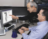
Peter Newman, a Senior Engineer at Eastman Kodak, uses Working Model to show other product engineers how complex mechanisms operate, and to design and analyze the many small levers, switches and components that go into each camera. Working Model’s automatic contact handling, shown in the high-speed switch below, saves Eastman Kodak countless hours during the design and analysis phase.
![[Camera Mechanism Picture]](ss_kodak.gif) Imagine trying to explain
to a small group the inner workings of a new complex camera mechanism
if they've never seen it before. Without the aid of a physical object
or motion picture, how would you tell them how it works? Even with the
use of slides and drawings, it has proven to be difficult and time-consuming
for viewers to comprehend.
Imagine trying to explain
to a small group the inner workings of a new complex camera mechanism
if they've never seen it before. Without the aid of a physical object
or motion picture, how would you tell them how it works? Even with the
use of slides and drawings, it has proven to be difficult and time-consuming
for viewers to comprehend.
The above scenario is all too familiar for Peter Newman, Senior Development Engineer for Eastman Kodak Company. As an expert on camera mechanisms, Newman collaborates on the mechanics of camera designs with fellow engineers and designers. The design engineers have expertise in many different areas and Newman often experienced difficulty verbally describing the specific workings of a design. He found that complex camera designs are better explained through the use of animation.
Fortunately for Newman, that difficulty is in the past. He solved his problem by finding a software program that lets him animate his mechanisms, resulting in a more realistic and interesting presentation to his engineering associates. He purchased Working Model, a desktop-based dynamics/kinematics software program from Design Simulation Technologies. Automatic Contact Handling. Intermittent contact is one aspect of camera mechanisms that Newman analyzes. To assist in his analysis, Newman initially utilized a workstation-based kinematics analysis software package to create rigid bodies known as links and connected them with joints. Since the links were joined together, it was difficult to get the workstation program to simulate the links coming apart. Yet, in the real world of camera design, that is just what happens as small parts (like latches and switches) open and close when the camera operates. From Newman's perspective, this intermittent contact needs to be easily simulated and is of key importance in visualizing the mechanism with the design engineers.
The workstation kinematics software was difficult to use in simulating intermittent contact. It required significant expertise, so Newman asked Kodak's kinematics expert to provide the animations he needed to communicate with other engineers. Because the expert's involvement was time consuming, Newman often resorted to using slides and drawings to present the mechanism with intermittent contact. "It would take long discussions to get my ideas across using static images," said Newman.
Desktop Dynamics.
It was at this frustrating point that Newman knew he needed a software package for a desktop system that could more easily animate mechanisms. By animating the mechanisms, he hoped to show the interaction of several parts and their effects on each other. This would help his colleagues understand the dynamics of a mechanism and the forces acting on the parts. "I looked for several years to find a product that does what Working Model does for me," said Newman. "So, you can imagine how astounded I was to see animation, plus intermittent contact and friction modeling performed so quickly and easily by Working Model. Other programs may have the capability, but they have to be programmed to perform what Working Model does automatically."
Working Model does not require special programming to simulate intermittent contact or friction. Using the Collide command, Newman sees how rigid bodies will collide and come apart and can evaluate the consequences. Friction is present in all rigid body contact and its coefficient can be easily changed.
In his collaborations with other design engineers, Newman was impressed with how many of his associates embraced the use of Working Model into their designs once they saw how easy it was to use.
Shutter Mechanism.
In one instance, Newman simulated a shutter mechanism for a new camera model. The initial design was created using the Unigraphics CAD program on a Hewlett Packard workstation. Building a model of the mechanism in Working Model took about two hours.
The first hour was spent in the CAD system generating 2D geometry from the 3D solid model suitable for use in Working Model. He then imported the geometry via DXF translators into Working Model.
The second hour involved building the mechanism in Working Model. The lines that represent one part were all selected to convert to a single rigid body. After all the rigid bodies were created, the joints and other elements such as springs and actuators were created. Immediate feedback that a mechanism had been built correctly was available, even for a partial mechanism, with a single click of the Run button. Default values are provided for all properties. Defining actual values was easy using the Properties window that changes as different objects are selected with the mouse. When the complete mechanism was built, graphs and digital readouts needed to measure results in the simulation were created and the force vectors that Newman wanted to visualize were defined.
The simulation was then run. Simple models will finish in several minutes but complex models can take over an hour to compute. Fortunately, the results are saved so they can be quickly replayed as a movie, over and over again. By playing the animation, Newman was able to explain to anyone how tile mechanism worked in just a few minutes. Without the animation, it would have taken much longer.
Working Model had created a graphic simulation to let Newman see the physical consequences of intermittent contact, motion, and force vectors, indicating how much force was being applied and in which direction. He was able to simulate the shutter speed that a particular shutter design would deliver. By changing the parameters in the model such as spring rates and masses, he was able to evaluate the effects of those changes and select a final design that met the design requirements. Each subsequent design iteration took only thirty minutes. Once perfected, the final design was used to build a working prototype. Excellent agreement was obtained between the results from Working Model and the prototype results.
Virtual vs. Physical Prototypes.
An alternative to analyzing designs in Working Model was to conduct tests on physical prototypes to make sure that the designs would meet requirements. Prototyping this way was both time-consuming and costly, since it took nearly two days to create physical models. Building a virtual prototype with Working Model took Newman only two hours.
When a physical prototype is built without being tested by software like Working Model, it may come back from the model shop inoperative. It can take several days to understand why it is inoperative. Afterwards, the prototype requires rebuilding, possibly going through several iterations that are, again, costly and time-consuming. Working Model gives insight into why initial designs of a model do not work, since all the forces in the mechanism can be visualized and measured. This allowed Newman to make his first iterations quickly, arriving at a final design about ten times faster than using prototypes alone.
According to Newman, using Working Model has provided the product design team with better feedback than ever before. They understand new mechanism dynamics much faster now, and since they are perfecting their designs more quickly, they are more productive. "I'm thrilled to finally have a product like Working Model," says Newman. "Our design team creates better designs faster because they are collaborating more successfully, my job is easier and Kodak is saving money."
 Quote
Quote Evaluation


