Dynamic Designer Motion
CAD Embedded Motion Simulation
Predicting Robot Performance
|
"What robot should I use for this specific application and path?" Facing untested conditions, Fanuc Robotics answers the question with motion simulation embedded in CAD instead of traditional assumptions and hand calculations. |
|
Recently Don Bartlett, a staff engineer at Fanuc Robotics, faced the issue of coming up with a new method for rating robots taking path dynamics into account. He needed to make sure a robot would perform the real path as required with the real payload, without overloading the robot. Educated guesses were not acceptable he needed to be sure the new rating system would insure that the robot would work properly for the customers application. Along with the CAD software and Fanucs own Virtual Controller product, Bartlett used Dynamic Designer Motion from Mechanical Dynamics, Inc. to understand and predict robot performance under previously untested conditions. Dynamic Designer is built into Fanucs CAD environment and produces validated results. That validation was key to Bartletts success. "I knew the answers were correct after I validated the Dynamic Designer results. I was confident in the simulation results I reported to the customer," said Bartlett. |
Predicting Performance"Will the new rating system allow customers to take advantage of the robots surplus capacity?" To find the answer, Bartlett employed a process that used both internally developed and commercial tools. An experimental robot path was programmed into the computer using Fanucs teach pendent product (Win TPE). Win TPE then communicated the path to the Fanuc Virtual Robot Controller product, which in turn generated joint kinematic properties for each robot joint as a function of time. Important to Bartlett was the fact that Dynamic Designer was completely embedded in the CAD system so the remainder of the project could be completed without ever leaving the CAD environment system. "The integration makes using Dynamic Designer easy because we can leverage our knowledge of the underlying CAD system," said Bartlett. "We can gain significantly expanded results without having to learn a whole new software package." With the assembled robot CAD data as the foundation, Dynamic Designers Intellimotion browser facilitated fast motion model development. Critical to the application was Dynamic Designers ability to use a series of data points to drive the robots joints. With the click of a button, the Dynamic Designer solution engine accurately simulated the motion of the robot based on Virtual Robot Controller data. Bartlett said, "One of the reasons we chose Dynamic Designer was because it is based on the proven ADAMS solver." The gross robot motion was reviewed through animations. Detailed motion was analyzed using torque and displacement graphs. These engineering data were plotted inside the CAD system using Dynamic Designer internal plotting and exported to Microsoft Excel for viewing and additional processing. Validating the ResultsTo make sure the physical device was modeled correctly, Bartlett first checked simple robot paths by moving one robot axis at a time and checking the results against the results of the hand-calculated dynamics equations.
Third, the robot path generated by Dynamic Designer was plotted and compared to the path generated by the Virtual Robot Controller. The plots were the same. With the validation complete, Bartlett was able to come up with a robot rating system that took advantage of the surplus robot capacity, without making any simplifying assumptions. Bartletts success with Dynamic Designer will lead to further use. "We are confident in the results we achieved with Dynamic Designer," Bartlett said. "Its integration with the CAD system will facilitate its use by many designers in our company. We would like to use it to predict component loads earlier in the design process." |
 Fanuc Robotics (Rochester Hills, MI) has developed a wide-ranging
robotic product line to help customers optimize labor, lower costs,
improve quality, and minimize waste. To achieve these goals, their
customers need to select the proper size robot for their application.
Unfortunately the current rating method is overly conservative because
it doesnt take the path dynamics into account.
Fanuc Robotics (Rochester Hills, MI) has developed a wide-ranging
robotic product line to help customers optimize labor, lower costs,
improve quality, and minimize waste. To achieve these goals, their
customers need to select the proper size robot for their application.
Unfortunately the current rating method is overly conservative because
it doesnt take the path dynamics into account. 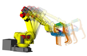 Instead
of using traditional assumptions and hand calculations, Bartlett
chose to use motion simulation technology. He relied on simulation
results to validate the customers robot path and payload.
Instead
of using traditional assumptions and hand calculations, Bartlett
chose to use motion simulation technology. He relied on simulation
results to validate the customers robot path and payload. 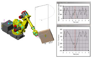 Second,
the shape of the Dynamic Designer torque curve was compared to the
shape of the Dynamic Designer acceleration curve. The two curve
shapes matched very well.
Second,
the shape of the Dynamic Designer torque curve was compared to the
shape of the Dynamic Designer acceleration curve. The two curve
shapes matched very well.  Quote
Quote Evaluation


